432 MHz Dish
Feed comparison
Content
1. Introduction
2. Disclaimer
3. Dipole in free space
4. Dual dipole
feed over a one
lambda circular reflector
5. Dual dipole
feed over a one
lambda square reflector
6.
DL4MEA loop feed
7.
OK1DFC loop feed
8.
XE1XA loop feed
9. One lambda
loop over a one lambda
circular reflector with BFR
10. SM6FHZ
BFR
loop
feed
11. Single
dipole over a one lambda
circular reflector
12. Single dipole over a
one
lambda circular reflector with BFR
13.
PY2BS Patch feed
14. Modified PY2BS
Patch feed
15.
ES5PC Patch feed
16. CT1DMK Annular Ring feed
17.
Conclusions
18.
Acknowledgments
19.
References
1. Introduction
When
looking in to the
details of choosing a feed for my 0.37 f/D dish on 432 MHz, I realized
it
was not easy to find the most suitable one. The data available for the
different alternatives was scarce and often important data was missing.
Even misleading data was found on some of the feed descriptions. I
came to the conclusion that it would be both interesting and beneficial
for the choice to look further on some of the alternatives.
The
good results on 23 cm with the W2IMU dual mode feed lead the thoughts
to finding something with similar radiation properties also for 432
MHz. Other criteria was size and ease of polarization rotation, stable
/ uncritical as well
as an easy to build and align design. With respect to radiation
properties, equal
beam
width
in E- and H-plane was a major criteria as well as the proper
illumination taper at +/- 64 degrees (edge of my dish). The W2IMU Dual
Mode feed has about -16.5 dB at +/-64 deg in both E and H-planes.
I
had already built the XE1XA Loop feed and wanted to know how it
performed. In the description, XE1XA
claims that this feed had equal beam width in E- and H-planes and that
he had used it in his 5 m, 0.45 f/D dish with success. It all
sounded very good to my ears, but I wanted to validate these statements.
I had no possibility to get it measured with any kind of decent
accuracy so simulation was to most attractive way forward.
When simulating the feed it turned out that the beam widths in E- and
H-plane were not similar at all. At this point I started to look around
for other suitable feeds for the job. I had also been looking at
Kildal's paper on the BFR for many years and realized that I now had
the tool to evaluate it on 432 MHz. After having done all kinds of
simulations and
evaluations I put on a BFR on my feed for testing. I am still in the
"on the air" evaluation phase.
NOTE!
All comparison is made with my 0.37 f/D dish in mind (64 degree edge
angle).
Starting
from a simple dipole in free space,
I made simulations in HFSS on the feeds I could find relevant design
data for. On some feeds I had to make some assumptions to get all the
needed mechanical dimensions. The simulation models are simplified as
much as I
thought was OK without jeopardizing the radiation performance accuracy.
The results from the simulations are probably on the optimistic side,
as any shortcomings in a physical realization will introduce
unsymmetries
and errors that will make the performance worse than simulated.
The feed performance data was put into W1GHZ "Phasepat.exe" (Ref. [1])
for further analysis of the "In Dish" performance.
The
Phase Center data are all referred to the surface of the reflector. The
Phase Center in the W1GHZ In Dish Performance graphs are referred to
the Phase Center I arrived at in my simulation. See comments about
Phase Center in the Conclusions
part.
I think this
comparison will give a good hint on the
characteristics of the feeds and aid in the choice of feed for me and for you as well, I hope.
Please
enjoy yourself when digging in to the data. I have very much enjoyed
making these simulations and arriving at the results and conclusions.
Lets go!
2.
Disclaimer
Please
bear in mind that the results below are from simulations and is not a
absolute universal truth! But it is good enough to serve as comparison
between the different feeds and to be used as basis for choosing a feed
for a particular application.
This
report is NOT intended to be a building description to follow step by
step to build a particular feed. The purpose is to make a survey among
the different feeds that has been described more or less detailed in
the HAM literature. For the feeds that are most interesting (best
performers) I may try to build and then report the dimensions used. For
the dimensions used for the simulations please drop me a mail, and you
will get the dimensions I used.
I
sincerely apologize for the mediocre picture resolution. As I did not
find a way to get the full resolution when transferring the pictures to
the web page composer, I have written all important data in the text as
well. See the graphs as a way to get a quick overview of the
performance of each individual feed examined.
The
results presented in this report are not allowed to be used
for any commercial purpose without explicit permission from
the
author. It may be used for Ham, non-commercial, purposes if
used
together with clear reference to the source of the
information. I.E. Normal polite journalistic standards.
3.
Dipole in free space
Description:
Half
lambda dipole in free space.
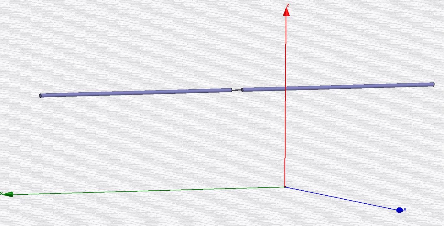
Figure
3:1; 432 MHz dipole model
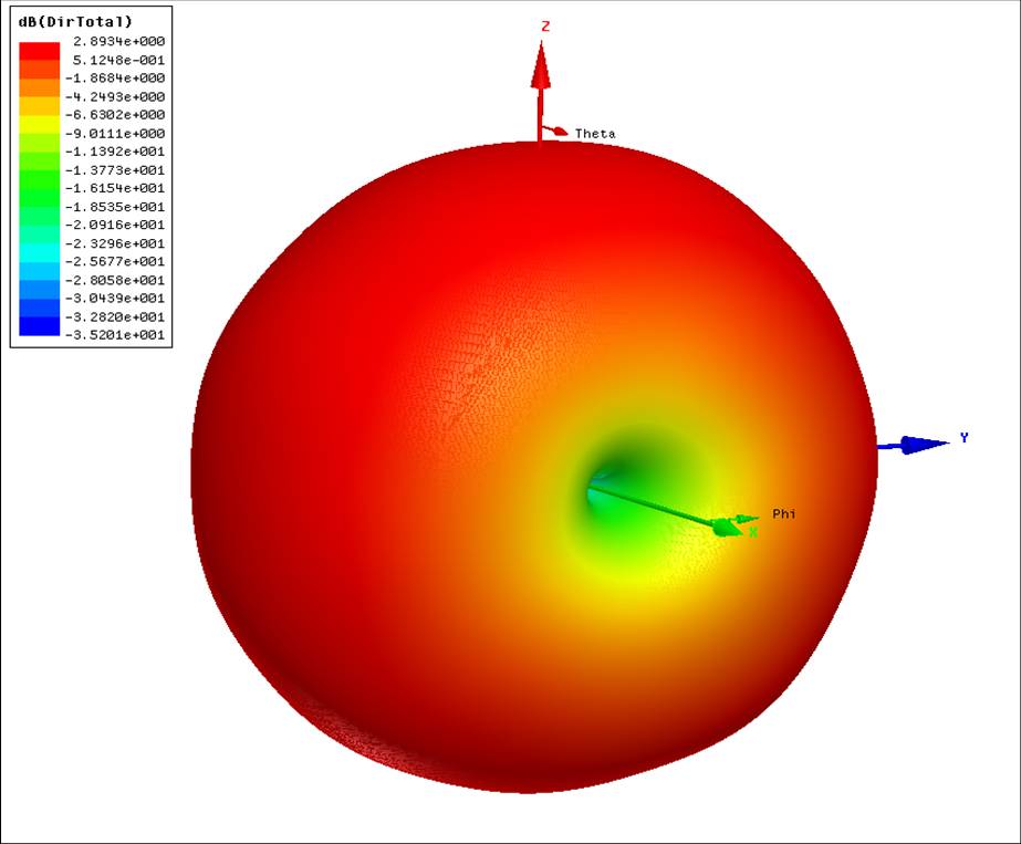
Figure
3:2; 432 MHz dipole 3D pattern
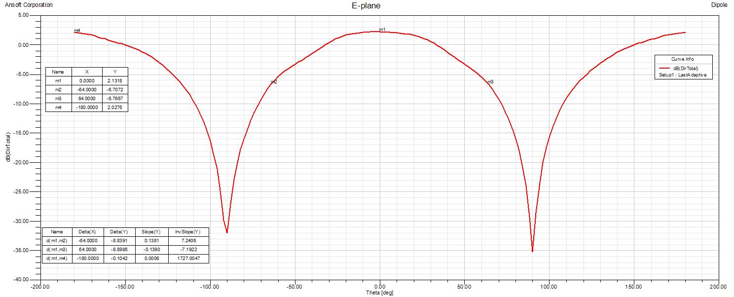
Figure
3:3; 432 MHz dipole
E-plane pattern
Figure
3:4; 432 MHz dipole
H-plane pattern
Comments:
I
used the dipole simulation to check the validity of the simulations. As
can be seen there is a slight disturbance in the H-plane cut (+/-0.4 dB
peak). This can
be seen also in the H-plane patterns on the feeds analyzed. This is an
minor artifact from the simulation and does not give any major impact
on the conclusions from the simulations. I have not spent any time on
optimizing the radiation boundary conditions in order to minimize the
disturbance. The average directivity of the
dipole is very close the the theoretical 2.15 dBi.
4.
Dual dipole feed over a one
lambda circular reflector
Description:
Two
half lambda dipoles quarter of lambda over a one lambda circular
reflector. The dipoles are separated one half lambda.
Figure
4:1; 432 MHz Dual Dipole feed model
Figure 4:2; 432
MHz
Dual Dipole feed 3D pattern
Figure 4:3; 432
MHz
Dual Dipole feed E-plane Co and Cross polarization patterns
Figure 4:4; 432
MHz
Dual Dipole feed E-plane Phase pattern
Figure 4:5; 432
MHz
Dual Dipole feed H-plane Co and Cross polar patterns
Figure 4:6; 432
MHz
Dual Dipole feed H-plane Phase pattern
Figure
4:7; 432 MHz
Dual Dipole feed in dish performance
Figure 4:8; 432
MHz
Dual Dipole feed in dish performance (10 wl diam)
Illumination characteristics:
E-plane:
-13.0 / -13.2 dB at +/- 64 degrees
H-plane: -12.8 / -12.9 dB
at +/- 64 degrees
Calculated directivity: +10 dBi
FBR:
14.9 dB
Phase center (relative to
reflector): +85 mm
Comments:
This is a
classic 432 MHz feed
for f/D 0.5 to 0.6 dishes. It is a derivative from feed No. 3 below,
the EIA standard gain antenna. It shows very well matched beam widths
in the E- and H-planes that will give balanced illumination of
the dish.
Clean pattern with good front to back ratio as well as very good cross
polar discrimination. A good choice even for
dishes deeper than 0.5 f/D if you would like a low noise antenna at the
expense of slightly reduced gain due to the under illumination that
will result. A drawback could be that it is slightly more cumbersome to
feed than a loop feed as it has two radiating elements. An more in detail analysis of
this feed including suggestions for improvements can
be found
here.
5.
Dual dipole feed over a one
lambda square reflector
Description:
Two
half lambda dipoles quarter of lambda over a one lambda square
reflector. The dipoles are separated one half lambda.
Figure 5:1; 432
MHz
Square Dual Dipole feed model
Figure 5:2; 432
MHz
Square Dual Dipole feed 3D pattern
Figure 5:3; 432
MHz Square Dual Dipole feed E-plane pattern
Figure 5:4; 432
MHz Square Dual Dipole feed E-plane Phase pattern
Figure
5:5; 432
MHz Square Dual Dipole feed H-plane pattern
Figure 5:6; 432
MHz Square Dual Dipole feed H-plane Phase pattern
Figure
5:7; 432
MHz Square Dual Dipole feed in dish performance
Figure 5:8; 432 MHz Square Dual Dipole feed in dish performance (10 wl
diam)
Illumination
characteristics:
E-plane:
-13.8 / -13.8 dB at +/- 64 degrees
H-plane: -14.4 / -15.1 dB
at +/- 64 degrees
Calculated directivity: +10.3 dBi
FBR:
14.8 dB
Phase center (relative to
reflector): +80 mm
Comments:
This is a another classic 432
MHz
feed for f/D 0.5 to 0.6 dishes. It is also called the EIA standard gain
antenna (Ref. [6]). It shows well matched beam
widths in the E- and H-planes but not as good as the dual dipole feed
with circular reflector. Clean pattern with good
front to back ratio. A good choice even
for dishes deeper than 0.5 f/D if you would like a low noise antenna at
the expense of slightly reduced gain due to the under illumination that
will result. A drawback could be that it is slightly more cumbersome to
feed than a loop feed as it has two radiating elements.
6.
DL4MEA loop feed
Description:
One lambda loop, one eights of
lambda above a 0.65
lambda circular reflector. Described as the DL4MEA loop feed at W1GHZ
On Line Antenna Book, Ref.[1]
Figure 6:1; 432
MHz DL4MEA loop feed model
Figure 6:2; 432
MHz DL4MEA loop feed 3D pattern
Figure 6:3; 432
MHz DL4MEA loop feed E-plane pattern
Figure 6:4; 432
MHz DL4MEA loop feed E-plane Phase pattern
Figure 6:5; 432
MHz DL4MEA loop feed H-plane pattern
Figure 6:6; 432
MHz DL4MEA loop feed H-plane Phase pattern
Figure
6:7; 432
MHz DL4MEA loop feed In dish performance
Figure 6:8; 432
MHz DL4MEA loop feed In dish performance (10 wl diam)
Illumination
characteristics:
E-plane:
-12.4 / -12.6 dB at +/- 64 degrees
H-plane: -7.3 / -6.7 dB
at +/- 64 degrees
Calculated directivity: +8.3 dBi
FBR:
11.3 dB
Phase center (relative to
reflector): +75 mm
Comments:
A
small and neat feed. Unfortunately the E-plane and H-plane beam widths
are not equal. The wide H-plane together with the relatively
narrow E-plane makes it difficult to find a suitable dish f/D to get a
good compromise between gain and low noise. The front to back ratio
(FBR) is mediocre, 11.3 dB while most
other feeds show
close to 15 dB. Good Cross polar discrimination and low phase
error as well as low feed blockage.
7.
OK1DFC loop feed
Description:
One
lambda loop one eighths
lambda above a half lambda diameter circular reflector with choke.
OK1DFC recalculated a OM6AA 13 cm design to 70 cm to fit his 0.4 f/D
dish.
Figure 7:1; 432
MHz OK1DFC loop feed model
Figure 7:2;
432
MHz OK1DFC loop feed 3D pattern
Figure
7:3; 432
MHz OK1DFC loop feed E-plane Co and Cross polar patterns
Figure 7:4; 432
MHz OK1DFC loop feed E-plane phase pattern
Figure 7:5; 432
MHz OK1DFC loop feed H-plane Co and Cross polar patterns
Figure 7:6; 432
MHz OK1DFC loop feed H-plane phase pattern
Figure
7:7; 432
MHz OK1DFC loop feed in dish performance
Figure 7:8; 432 MHz OK1DFC
loop feed in
dish performance (10 wl diam)
Illumination
characteristics:
E-plane:
-9.0 / -8.7 dB at +/- 64 degrees
H-plane: -7.1 / -6.9 dB
at +/- 64 degrees
Calculated directivity: +8.3 dBi
FBR:
14.5 dB
Phase center (relative to
reflector): +110 mm
Comments:
A
compact feed with good characteristics. This feed is mostly suitable to
use with deep dishes. Similar front to back ratio as the other good
feeds as well as reasonable equal radiation characteristics in E- and
H-planes. Construction seem to be fairly easy and the compact
dimensions
makes it easy to rotate in the polarization plane. A excellent choice
if
your dish is on the deep side!
8.
XE1XA loop feed
Description:
One lambda circumference loop,
one quarter of lambda over a one
lambda diameter circular reflector. Described by XE1XA in the "EME
newsletter" in 1986.
Figure 8:1; 432
MHz XE1XA loop feed model
Figure 8:2; 432
MHz XE1XA loop feed 3D pattern
Figure
8:3; 432
MHz XE1XA loop feed E-plane pattern
Figure 8:4; 432
MHz XE1XA loop feed E-plane phase pattern
Figure 8:5; 432
MHz XE1XA loop feed H-plane pattern
Figure 8:6; 432
MHz XE1XA loop feed H-plane phase pattern
Figure
8:7; 432
MHz XE1XA loop feed in dish performance
Figure8:8; 432
MHz XE1XA loop feed in dish performance (10 wl diam)
Illumination
characteristics:
E-plane:
-12.8 / -12.9 dB at +/- 64 degrees
H-plane: -8.5 / -7.3 dB
at +/- 64 degrees
Calculated directivity: +8.8 dBi
FBR:
15.5 dB
Phase center (relative to
reflector): +100 mm
Comments:
This
feed has the same drawbacks as all other dipole/loop based feeds;
unequal illumination in E- and H-planes. The front to back ratio is in
the same order as the other large reflector feeds. Clean radiation
pattern. Fairly easy to construct and to rotate in polarization.
9. One
lambda loop over a one lambda
circular reflector with BFR
Description:
One lambda loop, one quarter
of lambda over a one
lambda circular reflector with Beam Forming Ring (BFR) (diam. 20mm)
according to
Kildal, Ref [4] and [5]. This trial uses the original dimensions for
the BFR suggested by Kildal in his papers.
Figure 9:1; 432
MHz BFR loop feed model
Figure 9:2; 432
MHz BFR loop feed 3D pattern
Figure
9:3; 432
MHz BFR loop feed E-plane pattern
Figure
9:4; 432
MHz BFR loop feed E-plane Phase pattern
Figure
9:5; 432
MHz BFR loop feed H-plane pattern
Figure
9:6; 432
MHz BFR loop feed H-plane Phase pattern
Figure 9:7; 432
MHz BFR loop feed in dish performance
Illumination
characteristics:
E-plane:
-11.6 / -11.5 dB at +/- 64 degrees
H-plane: -12.7 / -11.6 dB
at +/- 64 degrees
Calculated directivity: +9.3 dBi
FBR:
13.4 dB
Phase center (relative to
reflector): +145 mm
Comments:
This
feed shows good equality in beam width between the E- and H-plane
thanks to the BFR. The FBR remains the same as without the BFR. This
makes it a good feed. The complexity is somewhat higher with the BFR
and the required volume increased from the feed without the BFR.
10. SM6FHZ
BFR
loop
feed
Description:
One
lambda loop over a one lambda circular reflector with an modified Beam Forming Ring
(BFR) (diam. 8mm) compared to the dimensions given by Kildal, Ref [4]
and [5] in order to
get a more
optimized and light weight design.
Figure 10:1; 432
MHz SM6FHZ BFR loop feed model
Figure 10:2; 432
MHz SM6FHZ BFR loop feed 3D pattern
Figure
10:3; 432
MHz SM6FHZ BFR loop feed E-plane pattern
Figure 10:4; 432
MHz SM6FHZ BFR loop feed E-plane phase pattern
Figure 10:5; 432
MHz SM6FHZ BFR loop feed H-plane pattern
Figure 10:6; 432
MHz SM6FHZ BFR loop feed E-plane phase pattern

Figure
10:7; 432
MHz SM6FHZ BFR loop feed in dish performance
Figure 10:8; 432 MHz SM6FHZ
BFR loop feed in
dish performance (10 wl diam)
Illumination characteristics:
E-plane:
-11.9 / -11.8 dB at +/- 64 degrees
H-plane: -12.3 / -11.5 dB
at +/- 64 degrees
Calculated directivity: +9.3 dBi
FBR:
13.3 dB
Phase center (relative to
reflector): +130 mm
Comments:
This
feed shows good
equality in beam width between the E- and H-plane thanks to the BFR.
The FBR remains the same as without the BFR. This makes it a good feed.
The complexity is somewhat higher with the BFR and the required volume
increased from the feed without the BFR. An more in detail analysis of
the above loop feeds including suggestions for further improvements can be found
here.
11.
Single dipole over a one lambda
circular reflector
Description:
Half
lambda dipole quarter of lambda over a one lambda circular reflector.
Figure 11:1; 432
MHz Single Dipole Feed model
Figure 11:2; 432
MHz Single Dipole Feed 3D pattern
Figure 11:3; 432
MHz Single Dipole feed E-plane pattern
Figure 11:4; 432
MHz Single Dipole feed E-plane Phase pattern
Figure 11:5; 432
MHz Single Dipole feed H-plane pattern
Figure 11:6; 432
MHz Single Dipole feed H-plane Phase pattern

Figure
11:7; 432
MHz Single Dipole feed in dish performance
Figure 11:8; 432
MHz Single Dipole feed in dish performance (10 wl diam)
Illumination characteristics:
E-plane:
-14.3 / -14.7 dB at +/- 64 degrees
H-plane: -7.1 / -7.0 dB
at +/- 64 degrees
Calculated directivity: +9.1 dBi
FBR:
15.7 dB
Phase center (relative to
reflector): +80 mm
Comments:
Similar
characteristics to the loop feed with one lambda reflector. The FBR is
slightly higher, but it does not give any real advantage when used as a
feed.
12.
Single dipole over a one
lambda circular reflector with BFR
Description:
Half
lambda dipole quarter of lambda over a one lambda circular reflector
with a Beam Forming Ring (BFR) (diam. 8mm) according to
Kildal, Ref
[4] and [5].
Figure 12:1; 432
MHz Single Dipole BFR Feed model
Figure 12:2; 432
MHz Single Dipole Feed 3D pattern
Figure 12:3; 432
MHz Single Dipole feed E-plane pattern
Figure 12:4; 432
MHz Single Dipole feed E-plane Phase pattern
Figure 12:5; 432
MHz Single Dipole feed H-plane pattern
Figure 12:6; 432
MHz Single Dipole feed H-plane Phase pattern

Figure
12:7; 432
MHz Single Dipole feed in dish performance
Figure 12:8; 432
MHz Single Dipole feed in dish performance (10 wl diam)
Illumination
characteristics:
E-plane:
-13.3 / -13.0 dB at +/- 64 degrees
H-plane: -10.8 / -10.9 dB
at +/- 64 degrees
Calculated directivity: +9.5 dBi
FBR:
14.2 dB
Phase center (relative to
reflector): +120 mm
Comments:
The
BFR shapes up the beam width but not to the same extent as for the loop
feed. The loop feed with BFR is still a better choice.
13.
PY2BS Patch feed
Description:
Dual
polarized patch over a 0.6 lambda circular reflector. The feed includes a tuning
disc for each polarization.
Figure 13:1; 432
MHz PY2BS Patch Feed model
Figure 13:2; 432
MHz PY2BS Patch Feed port isolation
Figure 13:3; 432
MHz PY2BS Patch Feed 3D total power directivity pattern
Figure 13:4; 432
MHz PY2BS Patch feed E-plane Co and Cross polarization patterns
Figure 13:5; 432
MHz PY2BS Patch feed E-plane phase pattern
Figure 13:6; 432
MHz PY2BS Patch feed H-plane Co and Cross polar patterns
Figure 13:7; 432
MHz PY2BS Patch feed H-plane phase pattern
Figure
13:8; 432
MHz PY2BS Patch feed in dish performance
Figure 13:9; 432
MHz PY2BS Patch feed in dish performance (10 wl diam)
Illumination
characteristics:
E-plane:
-11.5 / -11.5 dB at +/- 64 degrees
H-plane: -7.2 / -7.3 dB
at +/- 64 degrees
Calculated directivity: +7.8 dBi
FBR:
8.1 dB
Phase center (relative to
reflector): +25 mm
Comments:
Small
and compact feed. F/B ratio not as good as feeds with larger reflector.
Unequal dish illumination in E- and H-plane. Quite large
phase error in E-plane, probably due to loading of the patch
from
the probe and tuning disc. Low cross polar ratio, probably due to
loading of the patch from the other polarizations probe and tuning disc.
14. Modified
PY2BS Patch feed
Description:
Dual
polarized patch over a 0.6 lambda circular reflector with choke and low impedance
coaxial transformer.
Figure 14:1; 432
MHz modified PY2BS Patch Feed model
Figure 14:2; 432
MHz modified PY2BS Patch Feed isolation
Figure 14:3; 432
MHz modified PY2BS Patch Feed 3D total power directivity pattern
Figure 14:4; 432
MHz modified PY2BS Patch feed E-plane Co and Cross polarization patterns
Figure
14:5; 432
MHz modified PY2BS Patch feed E-plane Phase pattern
Figure 14:6; 432
MHz modified PY2BS Patch feed H-plane Co and Cross polar patterns
Figure 14:7; 432
MHz modified PY2BS Patch feed H-plane Phase pattern

Figure
14:8; 432
MHz modified PY2BS Patch feed in dish performance
Figure 14:9; 432
MHz modified PY2BS Patch feed in dish performance (10 wl diam)
Illumination characteristics:
E-plane:
-7.8 / -7.4 dB at +/- 64 degrees
H-plane: -7.3 / -7.2 dB
at +/- 64 degrees
Calculated directivity: +7.9 dBi
FBR:
15.3 dB
Phase center (relative to
reflector): +105 mm
Comments:
Small
and compact feed. F/B ratio, pattern and phase error improved with
choke.
15.
ES5PC Patch feed
Description:
Dual
polarized patch over a 0.72 lambda circular reflector (Ref [7]). The design originates from
W0LMD, (Ref. [8], according to ES5PC.
Figure 15:1; 432
MHz ES5PC Patch Feed model
Figure 15:2; 432
MHz ES5PC Patch Feed isolation
Figure 15:3; 432
MHz ES5PC Patch Feed 3D total power directivity pattern
Figure 15:4; 432
MHz ES5PC Patch feed E-plane directivity Co and Cross polarization
patterns
Figure 15:5; 432
MHz ES5PC Patch feed E-plane Co-polar phase pattern
Figure 15:6; 432
MHz ES5PC Patch feed H-plane Co and Cross polarization patterns
Figure 15:7; 432
MHz ES5PC Patch feed H-plane Co polar phase pattern
Figure
15:8; 432
MHz ES5PC Patch feed in dish performance
Figure 15:9; 432
MHz ES5PC Patch feed in dish performance (10 wl diam)
Illumination
characteristics:
E-plane:
-12.7 / -15.1 dB at +/- 64 degrees
H-plane: -8.1 / -8.1 dB
at +/- 64 degrees
Calculated directivity: +8.8 dBi
FBR:
9.6 dB
Phase center (relative to
reflector): +40 mm
Comments:
Small
and compact feed. F/B ratio not as good as feeds with larger reflector.
Unequal dish illumination in E- and H-plane. Large phase error in
E-plane, probably due to the loading of the patch from the
probe.
Nice isolation between the ports for the two
polarizations.
16. CT1DMK
Annular Ring feed
Description:
Dual
polarized one lambda capacitively loaded ring 0.09 lambda over a 0.62
lambda circular reflector (Ref [9]).
Figure 16:1; 432
MHz CT1DMK Annular Ring Feed model
Figure 16:2; 432
MHz CT1DMK Annular Ring Feed 3D total power directivity pattern
Figure 16:3; 432
MHz CT1DMK Annular Ring feed E-plane directivity Co and Cross
polarization patterns
Figure 16:4; 432
MHz CT1DMK Annular Ring feed E-plane Co-polar phase pattern
Figure 16:5; 432
MHz CT1DMK Annular Ring feed H-plane Co and Cross polarization patterns
Figure 16:6; 432
MHz CT1DMK Annular Ring feed H-plane Co polar phase pattern
Figure
16:7; 432
MHz CT1DMK Annular Ring feed in dish performance
Illumination
characteristics:
E-plane:
-12.1 / -14.6 dB at +/- 64 degrees
H-plane: -7.9 / -7.7 dB
at +/- 64 degrees
Calculated directivity: +6.7 dBi
FBR:
6.5 dB
Phase center (relative to
reflector): +80 mm
Comments:
0.62
lambda reflector size. The Annular Ring, used in this feed, is a
derivative of the patch radiator with the inner (center) part removed.
It is sometimes used in antennas for cellular systems. This Annular
Ring is capacitively loaded in order to match the impedance. It is fed
at a high impedance point at the rim of the fictive
"patch". Unequal dish illumination in E- and H-plane. Large
phase
error in
E-plane at large angles, probably due to the loading of the
patch
from the
probe
and tuning capacitance.
No isolation data between the ports for the two
polarizations is presented for this feed, as it is simulated as CT1DMK
recommends, with the unused port left open. The heavy loading from the
tuning also gives high cross polar radiation. The low front to back
ratio will steal power form the main beam and consequently not reach
the dish surface.
17. Conclusions
Table of summary:
| Feed type |
Level at +/- 64 deg (E-plane) [dB] |
Level at +/- 64 deg (H-plane) [dB] |
Directivity [dBi] |
FBR [dB] |
Phase center [mm] |
Comments |
| W2IMU
feed |
-16.5/-16.5 |
-16.5/-16.5 |
|
28 |
|
For
comparison |
| Dual
Dipole (square reflector) |
-13.8/-13.8 |
-14.4/-15.0 |
10.3 |
14.8 |
+80 |
|
| Dual
Dipole (square reflector) w. W2IMU |
|
|
|
|
|
TBD |
| Dual
Dipole (circular reflector) |
-13.2/-13.2 |
-12.6/-13.0 |
10.1 |
15.2 |
+85 |
|
| DL4MEA
loop |
-12.4/-12.6 |
-7.3/-6.7 |
8.7 |
11.3 |
+75 |
Compact
feed. |
| OK1DFC
loop |
-8.7/-9.0 |
-6.9/-7.1 |
8.3 |
14,5 |
+110 |
Compact
feed for deep dishes |
| XE1XA
loop |
-12.8/-12.9 |
-8.5/-7.3 |
8.8 |
15.5 |
+100 |
|
| BFR
Loop 20 mm |
-11.8/-11.7 |
-12.7/-11.6 |
9.3 |
13.4 |
+145 |
|
| SM6FHZ BFR Loop |
-11.9/-11.8 |
-12.3/-11.5 |
9.3 |
13.3 |
+130 |
|
| PY2BS
patch |
-11.5 / -11.5 |
-7.2/-7.3 |
7.8 |
8.1 |
+25 |
Very
compact feed. |
| PY2BS
modified patch |
-7.8 / -7.4 |
-7.3 / -7.2 |
7.9 |
15.3 |
+105 |
|
| ES5PC
patch |
-12.7 / -15.1 |
-8.1 / -8.1 |
8.8 |
9.6 |
+40 |
|
| CT1DMK
Annular Ring |
-12.1 / -14.6 |
-7.9 / -7.7 |
6.7 |
6.5 |
+80 |
|
| Dipole
over reflector |
-14.3/-14.7 |
-7.1/7.0 |
9.1 |
15.7 |
+80 |
|
| Dipole
over reflector with BFR |
-13.3/-13.0 |
-10.8/-10.9 |
9.5 |
14.2 |
+120 |
|
There
is a clear difference between feeds with a one lambda reflector and
feeds with a smaller reflector when it comes to beam width and front to
back ratio. If you use
a loop or a single dipole as the radiating element does not matter, the
characteristics are about the same for both. Both have unequal beam
with in the E- and H-planes with the H-plane to be the wider one.
One
statement I saw in a description for a loop feed was that you could
adjust the beam width in E- and H-plane by making the loop oval. This
is not correct. It does hardly make any difference at all. You can go
the the extreme of a loop; the folded dipole and still have about the
same E- and H-plane patterns.
In
order to equalize the the beam widths in E- and H-planes one can use
one more dipole fed in phase, a Beam Forming Ring (BFR) or a choke
(baffle) on
the reflector. The two first ones makes the H-plane more narrow to
match the E-plane. The choke makes the E-plane wider to match the
H-plane.
The feeds with a more narrow beam width and
reasonably
equal illumination in the E- and H-planes are the Dual Dipole feeds and
the Loop feeds comprising a BFR. The BFR-loop feeds have slightly wider
beam widths in both planes compared to the dual dipole feeds.
The
only feeds examined with wider beam width and
reasonably equal illumination in the E- and H-planes is the OK1DFC Loop
feed and the modified PY2BS Patch feed. These two feeds fit well into a
deep dish.
None of the examined feeds are as narrow
as the W2IMU Dual Mode feed used as a reference.
The
far field phase error ranges from very good to mediocre to bad on the
feeds examined. Some of the Dual Polarized feeds examined suffer from
phase
distortion in the far field. This seem to be the price you have to pay
for Dual Polarization feature in some cases.
The center of rotation for
all feeds is in the center of the
reflector (X,Y-axises) and in
the plane of the phase center (Z-axis). The position of the phase
center has
been empirically determined by running simulations on different center
of rotation (Z-axis). The Phase center has been chosen as a best
compromise
between E- and H-plane phase error. The Phase center data in this report is always referred to the
front surface of the reflector. From
experience with sun noise measurements
on my XE1XA feed in my 0.37 f/D dish; if you are within 3 to 5 cm from
the phase center you can hardly see any deviation in sun
noise. This is
at the 11 dB level on 432 MHz.
Further work that could be
done includes:
- Simulations
on physical
realizations on some of the above feeds.
- Simulation
on the Dual Dipole feed with a W2IMU Dual Mode feed horn in the center
(as used by many active Moonbouncers today) both on impact on the 70
cm performance as well as impact on the 23 cm performance.
- Look
into other possible 70 cm
feed ideas, especially for deep dishes, striving for very good
efficiency and low noise.
18. Acknowledgments
I
would like to thank all the "inventors" (CT1DMK, ES5PC, DL4MEA, OK1DFC
and
PY2BS) of the feeds that I have analyzed for letting me publish the
results here. I would also like to send a big thank you to G3LTF,
Peter, VK3UM, Doug and W1GHZ, Paul for the support and discussions
about the results and the form
of this presentation. Your support and comments have been
indispensable along the way. Finally, I send my sincere appreciation to
my colleagues at QRL (Anders, Lars, Anders, Henrik, Andreas, Ola and
Anders)
for putting up with my ever lasting questions about simulations,
pitfalls and coordinate systems. Without their support I would never
had come through this work. And I do not forget to thank my lovely
family that had been suffering from heavy loading of our common
computer resources from the endless simulations, disrupting all other
activities
on the computer and the Internet.
19. References
[1]
W1GHZ Antenna Book on line: http://www.w1ghz.org/
[2]
OK1DFC web page: http://www.ok1dfc.com/EME/technic/432feed/432feed.htm
[3]
432 MHz and above News, Sept 1986, Vol 14 #10, The XE1XA feed
description can also be found at PA3CSG's web page.
[4)
Dipole-Disk Antenna with Beam-Forming Ring, Per-Simon
Kildal, Svein A. Skyttemyr, IEEE Transactions on Antennas and
Propagation, Vol. AP-30, No. 4, July 1982, page 529 - 534.
[5]
A Small Dipole-Fed Resonant Reflector Antenna with High Efficiency, Low
Cross Polarization, and Low Side lobes, Per-Simon
Kildal, IEEE
Transactions on Antennas and Propagation, Vol.
AP-33, No. 12, December 1985, page 1386 - 1391.
[6]
Antenna Performance Measurements, Dick Turrin, W2IMU, QST November
1974, page 35 to 41.
[7] ES5PC Patch feed
description: http://www.comnetsys.eu/files/ES5PC/432MHzPatchFeed/432MHz_Patch.pdf
and http://www.comnetsys.eu/files/ES5PC/432MHzPatchFeed/
[8] W0LMD
Patch feed
description: http://www.samuelraileyefurd.com/interestingthings/ultimatecharger/dish-feed-u.html
[9]
CT1DMK Annular Ring feed
description: http://www.qsl.net/ct1dmk/70cm_loop.pdf

Updated
May 31st, 2011. © Ingolf
Larsson, SM6FHZ, December, 2010
http://www.2ingandlin.se/SM6FHZ.htm