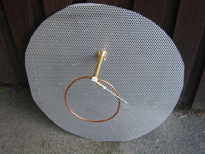
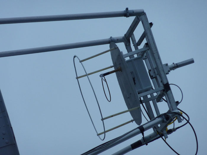
SM6FHZ 432 MHz BFR Loop Feed


1. Introduction


When looking in to the details of choosing a feed for my 0.37 f/D dish on 432 MHz, I realized it was not easy to find the most suitable one. The data available for the different alternatives was scarce and often important data was missing. Even misleading data was found on some of the feed descriptions.

I had already built the XE1XA Loop feed and wanted to know how it performed. In the description, XE1XA claims that this feed had equal beam width in E- and H-planes and that he had used it in his 5 m, 0.45 f/D dish with success. It all sounded very good to my ears, but I wanted to validate these statements. I had no possibility to get it measured with any kind of decent accuracy so simulation was to most attractive way forward. When simulating the feed it turned out that the beam widths in E- and H-plane were not similar at all.

I started to set up criteria for the performance I wanted from my feed. With respect to radiation properties, equal beam width in E- and H-plane was a major criteria as well as the proper illumination taper at +/- 64 degrees (edge of my dish). Low Cross Polar radiation and low radiation in the area where the ground is seen by the feed as well as low back lobe radiation (at least below -13 to -14 dB, in order to minimize the power lost from radiation in other directions than towards the dish surface).

At this point I started to look around for other suitable feeds for the job. I had also been looking at Kildal's paper on the BFR for many years and suddenly realized that I now had the tool to evaluate it on 432 MHz. The simulations on several other feeds showed a lot of interesting solutions and I got some inspiration and ideas from that as well.

After having done all kinds of simulations and evaluations I put on a BFR on my existing XE1XA Loop feed for testing. I am still in the "on the air" evaluation phase.


NOTE! All comparison is made with my 0.37 f/D dish in mind (64 degree edge angle).

The simulation models are simplified as much as I thought was OK without jeopardizing the radiation performance accuracy. The results from the simulations are probably on the optimistic side, as any shortcomings in a physical realization will introduce asymmetries and errors that will make the performance worse than simulated. The feed performance data was put into W1GHZ "Phasepat.exe" (Ref. [1]) for further analysis of the "In Dish" performance.

The Phase Center data are all referred to the surface of the reflector. The Phase Center in the W1GHZ In Dish Performance graphs are referred to the Phase Center I arrived at in my simulation. See comments about Phase Center in the Conclusions part.

The efficiency tables in white text on black background (Fig 3:7, 4:7 and 5:7), are screen dumps from W1GHZ Phasepat.exe DOS window execution. In them you can read the calculated efficiency numbers for each calculated point in detail. Note however that some of the columns with efficiency numbers are the complementary efficiency measure compared to the number presented in the graphs (i.e. Illum, Spillover and Blockage). The very last column named "Phase" is the total efficiency including any phase error and can be compared the column named "TOTAL" that show the total efficiency without any phase error.

I hope this description will give the reader a good hint on the characteristics of the feeds, a lot of inspiration and aid in the choice of feed.

Please enjoy yourself digging in to the data. I have very much enjoyed making these simulations and arriving at the results and conclusions.

2. Disclaimer

Please bear in mind that the results below are from simulations and is not an absolute universal truth! But it is good enough to serve as comparison between the different feeds and to be used as basis for choosing a feed for a particular application.

This report is a more detailed description to follow in order to build a these feeds and contains the most important dimensions used. Some dimensions are intentionally left out, as the builder may have their own ideas on how to make these parts. In most cases they
have not any major impact on the radiation performance.

I sincerely apologize for the mediocre picture resolution. As I did not find a way to get the full resolution when transferring the pictures to the web page composer, I have written all important data in the text and tables as well. See the graphs as a way to get a quick overview of the performance of each individual feed examined.

The results presented in this report are not allowed to be used for any commercial purpose without explicit permission from the author. It may be used for Ham, non-commercial, purposes if used together with clear reference to the source of the information. I.E. Normal polite journalistic standards.


3. XE1XA Loop Feed

Description:

One lambda circumference loop, one quarter of lambda over a one lambda diameter circular reflector. Described by XE1XA in the "EME newsletter" in 1986 (Ref. [2]).

432 MHz XE1XA loop feed model
Figure 3:1; 432 MHz XE1XA loop feed model

432 MHz XE1XA loop feed 3D pattern
Figure 3:2; 432 MHz XE1XA loop feed 3D pattern

432 MHz XE1XA loop feed E-plane pattern
Figure 3:3; 432 MHz XE1XA loop feed E-plane pattern

XE1XA loop feed E-plane phase
Figure 3:4; 432 MHz XE1XA loop feed E-plane phase pattern

432 MHz XE1XA loop feed H-plane pattern
Figure 3:5; 432 MHz XE1XA loop feed H-plane pattern

XE1XA loop feed H-plane phase
Figure 3:6; 432 MHz XE1XA loop feed H-plane phase pattern


XE1XA loop feed efficiency table
Figure 3:7; 432 MHz XE1XA loop feed efficiency table for 10 wl dish diameter

XE1XA Loop feed in dish performance                        XE1XA Loop feed inDich 10wl
Figure 3:8; 432 MHz XE1XA loop feed in dish performance                                                                Figure 3:9; 432 MHz XE1XA loop feed in dish performance (10 wl diam)

Illumination characteristics:
E-plane: -12.8 / -12.9 dB at +/- 64 degrees
H-plane: -8.5 / -7.3 dB at +/- 64 degrees
Calculated directivity: +8.8 dBi
FBR: 15.5 dB
Phase center (relative to reflector): +100 mm


Comments:
This feed has the same drawbacks as all other dipole/loop based feeds; unequal illumination in E- and H-planes. The front to back ratio is in the same order as the other large reflector feeds. Clean radiation pattern. Fairly easy to construct and to rotate in polarization.


4. SM6FHZ BFR Loop Feed

Description:

One lambda circumference loop, one quarter of lambda over a one lambda diameter circular reflector with an modified Beam Forming Ring (BFR) (diam. 8mm) compared to the dimensions given by Kildal, Ref [3] and [4] in order to get a more electrically and mechanically optimized light weight design.

432 MHz moified BFR loop feed model
Figure 4:1; 432 MHz SM6FHZ BFR loop feed model

432 MHz modified BFR loop feed 3D pattern
Figure 4:2; 432 MHz SM6FHZ BFR loop feed 3D pattern

432 MHz SM6FHZ BFR loop feed E-plane pattern
Figure 4:3; 432 MHz SM6FHZ BFR loop feed E-plane pattern

SM6FHZ BFR loop phase E-plane
Figure 4:4; 432 MHz SM6FHZ BFR loop feed E-plane phase pattern

432 MHz SM6FHZ BFR loop feed H-plane pattern
Figure 4:5; 432 MHz SM6FHZ BFR loop feed H-plane pattern

SM6FHZ BFR loop H-plane phase
Figure 4:6; 432 MHz SM6FHZ BFR loop feed H-plane phase pattern


SM6FHZ BFR Loop feed efficiency table
Figure 4:7; 432 MHz SM6FHZ BFR loop feed efficiency table for 10 wl dish diameter

SM6FHZ BRF Loop feed in dish performance                         SM6FHZ BFR Loop inDish 10wl
Figure 4:8; 432 MHz SM6FHZ BFR loop feed in dish performance                                                      Figure 4:9; 432 MHz SM6FHZ BFR loop feed in dish performance (10 wl diam)

SM6FHZ BFR Loop feed with choke inDish performance 15 wl
Figure 4:10; 432 MHz SM6FHZ BFR loop feed in dish performance (15 wl diam)


Illumination characteristics:
E-plane: -11.9 / -11.8 dB at +/- 64 degrees
H-plane: -12.3 / -11.5 dB at +/- 64 degrees
Calculated directivity: +9.3 dBi
FBR: 13.3 dB
Phase center (relative to reflector): +130 mm

Comments:
This feed shows good equality in beam width between the E- and H-plane thanks to the BFR. The FBR remains the same as without the BFR. This makes it a good feed. The complexity is somewhat higher with the BFR and the required volume increased from the feed without the BFR.


5. SM6FHZ BFR Loop Feed with choke

Description:

One lambda circumference loop, one quarter of lambda over a one lambda diameter circular reflector comprising an 50 mm high choke (baffle) and including an 8mm diameter Beam Forming Ring (BFR).

432 MHz moified BFR loop feed choke model
Figure 5:1; 432 MHz SM6FHZ BFR loop feed with choke model

432 MHz SM6FHZ BFR loop feed 3D pattern
Figure 5:2; 432 MHz SM6FHZ BFR loop feed with choke 3D pattern

432 MHz SM6FHZ BFR loop feed E-plane pattern
Figure 5:3; 432 MHz SM6FHZ BFR loop feed with choke E-plane pattern

SM6FHZ BFR loop phase E-plane
Figure 5:4; 432 MHz SM6FHZ BFR loop feed with choke E-plane phase pattern

432 MHz SM6FHZ BFR loop feed H-plane pattern
Figure 5:5; 432 MHz SM6FHZ BFR loop feed with choke H-plane pattern

SM6FHZ BFR loop H-plane phase
Figure 5:6; 432 MHz SM6FHZ BFR loop feed with choke H-plane phase pattern


Efficiency table for SM6FHZ Loop Feed with choke
Figure 5:7; 432 MHz SM6FHZ BFR loop feed with choke efficiency table for 10 wl dish diameter

SM6FHZ BRF Loop choke feed in dish performance                         SM6FHZ BFR Loop choke inDish 10wl
Figure 5:8; 432 MHz SM6FHZ BFR loop choke feed in dish performance                                      Figure 5:9; 432 MHz SM6FHZ BFR loop choke feed in dish performance (10 wl diam)


In dish performance 15 wl BFR loop with choke
Figure 5:9; 432 MHz SM6FHZ BFR loop choke feed in dish performance (15 wl diam)

Illumination characteristics:
E-plane: -12.3 / -12.1 dB at +/- 64 degrees
H-plane: -13.2 / -12.4 dB at +/- 64 degrees
Calculated directivity: +9.3 dBi
FBR: 16.0 dB
Phase center (relative to reflector): +130 mm

Comments:
This feed shows good equality in beam width between the E- and H-plane thanks to the BFR. The FBR improves compared to without the choke. This makes it a very good feed for dishes with a f/D from 0.4 to 0.5. When the impact of blockage is minimized, as on a larger (e.g. 15 wl diameter) dish, it's performance will be an challenge to beat. The complexity is somewhat higher with the choke. The spillover is reduced compared to the BFR Loop Feed without the choke. The lower spillover together with the improved efficiency makes it one of the best 70 cm feeds (for f/D's in the 0.4 to 0.5 region) simulated so far.


6. Conclusions

Table of summary:
Feed type Level at +/- 64 deg (E-plane) [dB] Level at +/- 64 deg (H-plane) [dB] Directivity [dBi] FBR [dB] Efficiency, max [%] Spillover, at max eff [%] Spillover, at max eff [K] Efficiency at 0.392 [%] Spillover, at 0.392 [%] Spillover, at 0.392 [K] Phase center [mm] Comments
XE1XA loop -12.8/-12.9 -8.5/-7.3 8.8 15.5 71.9 / 0.43 16.2 35 71.5 12.5 27 +100  
SM6FHZ BFR Loop  -11.9/-11.8 -12.3/-11.5 9.3 13.3 75.6 / 0.48 13.6 29 71.7 7.2 14 +130  
SM6FHZ BFR Loop with choke -12.3 / -12.1 -13.2/-12.4 9.7 16 76.3 / 0.48 11.6 25 71.6 5.4 11 +130  


Efficiencies in the table refers to a 10 wl diameter dish. The efficiency values are read directly from W1GHZ PhasePat data and are subject to the note that Paul has in his chart; "REAL WORLD at least 15% lower". The spillover noise temperature figures have been estimated by using VK3UM EMECalc, just to give another reference to the improvement.

The evolution in performance in a 10 wl dish can be clearly seen below starting with the XE1XA Loop feed going via the SM6FHZ BFR Loop feed to the FHZ BFRLCF.

XE1XA Loop feed inDish performance in 10 wl dish  SM6FHZ BFR Loop feed inDish performance in 10 wl dish  SM6FHZ BFR Loop feed with choke inDish performance in 10 wl dish


It has been demonstrated that in order to equalize the the beam widths in E- and H-planes one can use one more dipole fed in phase, a Beam Forming Ring (BFR) or a choke (baffle) on the reflector. The two first ones makes the H-plane more narrow to match the E-plane. The choke makes the E-plane wider to match the H-plane. Combining the BFR with a choke leads to further improvements both in increased efficiency as well as in noise performance (reduced spillover). The increase in E-plane beam width does not show up when the BFR already is in place. I have no explanation for that. What the choke does here is to clean up the unwanted side lobes in the rear hemisphere of the feed, including the back lobe. The cross polar radiation in the H-plane is also strongly reduced by the choke. This happens also in the E-plane to a smaller extent.

As seen from the table, the maximum efficiency increases from the XE1XA Loop feed to the SM6FHZ BFR Loop feed (FHZ BFRLF) to the SM6FHZ BFR Loop feed with choke 
(FHZ BFRLCF). The largest jump in efficiency is from the XE1XA Loop feed to the SM6FHZ BFR Loop feed, but here the f/D for maximum efficiency goes from 0.43 to 0.48. At the same time the spillover both at maximum efficiency as well as at a constant f/D (0.392) improves. At the constant f/D it even improves dramatically, from 12.5% to 5.4%. This corresponds to an noise temperature contribution change from 27 K to 11 K from the spillover. The efficiency at 0.392 f/D is almost constant for the three feeds but the spillover decreases results in a much more quiet antenna.

The center of rotation for all feeds is in the center of the reflector (X,Y-axises) and in the plane of the phase center (Z-axis). The position of the phase center has been empirically determined by running simulations on different center of rotation (Z-axis). The Phase center has been chosen as a best compromise between E- and H-plane phase error. The Phase center data in this report is always referred to the front surface of the reflector. From experience with sun noise measurements on my XE1XA feed in my 0.37 f/D dish; if you are within 3 to 5 cm from the phase center you can hardly see any deviation in sun noise. This is at the 11 dB level on 432 MHz.

Further work that could be done includes:


7. Realization

The XE1XA Loop feed was built according to the original description in Ref. [2]. The tube dimensions for the gamma match was slightly modified to fit the tubes available to me.

XE1XA Loop feed

Adding the BFR to the existing feed was no rocket science. I used four pieces of 18 mm plastic tubes (used for carrying electrical wires in walls etc.) as supports. The BFR was made from 8 mm aluminum tubing made into a 695 mm mean diameter ring (=687 mm inner) and a short piece of aluminum rod together with two small hose-clamps to join the ends together. The BFR is 312 mm above the reflector surface (center of ring).

SM6FHZ BFR Loop feed

Adding the choke is still to be implemented on my feed.


8. Acknowledgments


I would like to send a big thank you to G3LTF, Peter, VK3UM, Doug and W1GHZ, Paul for the support and discussions about the
results and the form of this presentation. Your support and comments have been indispensable along the way. Finally, I send my sincere appreciation to my colleagues at QRL (Anders, Lars, Anders, Henrik, Andreas, Ola and Anders) for putting up with my ever lasting questions about simulations, pitfalls and coordinate systems. Without their support I would never had come through this work. And I do not forget to thank my lovely family that had been suffering from heavy loading of our common computer resources from the endless simulations, disrupting all other activities on the computer and the Internet.

9. References

[1] W1GHZ Antenna Book on line:  http://www.w1ghz.org/

[2] 432 MHz and above News, Sept 1986, Vol 14 #10, The XE1XA feed description can also be found at PA3CSG's web page.

[3] Dipole-Disk Antenna with Beam-Forming Ring, Per-Simon Kildal, Svein A. Skyttemyr, IEEE Transactions on Antennas and Propagation, Vol. AP-30, No. 4, July 1982, page 529 - 534.

[4] A Small Dipole-Fed Resonant Reflector Antenna with High Efficiency, Low Cross Polarization, and Low Side lobes,
Per-Simon Kildal, IEEE Transactions on Antennas and Propagation, Vol. AP-33, No. 12, December 1985, page 1386 - 1391.


Updated March 27th, 2011.  © Ingolf Larsson, SM6FHZ, March, 2011              http://www.2ingandlin.se/SM6FHZ.htm