Formatting
transmitting tubes
and
associated questions
You
need to format or "burn in" old transmitting tubes that have been on
the shelf for some time in order to avoid arcing and the risk of
destroying them. You can find descriptions and procedures on how to do
this on several places on the Internet. SM5BSZ among others. This is my
way of dealing with this process.
I
use the old HAIR-rule: Heater - Anode - Idle - RF . Start with heater
voltage only, then apply anode voltage, after that run idle current in
the tube and finally apply RF to the tube. This rule has been
successfully used on many different tubes over the years; 4CX250B,
4CX350A, GS23b, TH308, TH328, TH338, YD1277 etc.
Formatting
process
Take
the
following steps in order to format transmitting tubes that have been on
the shelf for a long time:
- Run
the tube with heater voltage only for at least 24 hours. You may start
with lower heater voltage than specified for a few hours (may be
disputed due to the risk of poisoning the cathode). NOTE!
During this and all following operations, full cooling air flow shall
be applied to the tube, even to the cathode area as
specified/recommended by the tube manufacturer.
- Apply
then HV
to the tube with series resistor (SM6EHY recommends 100 k). I use
different resistors depending
on the tube. 33 kohm is a good start. Start with a low voltage, say 500
V and work your way up in 300 to 500 V increments until you have
reached the voltage level you will use in normal operation. Stay at
each level for half an hour to an hour. For tetrodes this step shall be
done without screen voltage applied.
- Connect
the high voltage line without the current limiting resistor to the
tube. For tetrodes also apply screen voltage, you may use a reduced
value (say 70 % of normal). Start again at 500 V anode voltage and
adjust the bias to a small anode current (say 50 mA). Let the tube run
for an hour. Increase the anode current to say 100 mA (depending on the
tube in question). Run for half an hour. Reduce the anode current to
zero again and increase the anode voltage by 300 to 500 V. Adjust the
bias for 50 mA anode current and run for half an hour. Increase the
anode current to 100 mA again. Continue this procedure until you are
close to your desired operating anode voltage. Increase the anode
current to a higher value and let the tube run. The anode of the tube shall be
warm. NOTE! DO NOT
touch the anode to check. Do not even think about it.
Measure the outlet air
temperature instead. The outlet air temperature shall increase
considerably, but
make sure you do not over heat the tube. I usually go up to 50 degrees
C of air outlet temperature. I measure the air outlet temperature by
the use of the outdoor sensor of a regular indoor/outdoor digital
thermometer.
- Decrease
the anode voltage again to a moderate value, say 60 % of the desired
operating voltage. Adjust the bias to a low but proper anode current.
Apply a small amount of RF, increasing the anode current slightly. Run
for a few minutes. Increase the RF drive somewhat to give an slightly
hinger anode current. The RF may be pulsed or why not send "TEST DE
YOUR CALL" in CW. Increase the anode voltage in moderate steps, say 100
to 200 V t a time and run for some time. Repeat until you are close to
your desired operating voltage. This may take a few hours to get there.
Monitor the outlet cooling air temperature again in order to have a
check on the anode
temperature. Keep it at about 50 deg C. Run the tube extensively at
this reduced power level on for instance local rag chaw QSO's for some
time, the more the better.
- You
should now be ready to run the tube at full data.
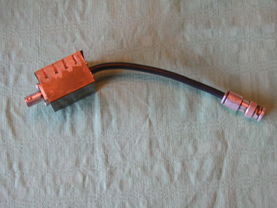 Limiting resistor box with MHV
connectors.
Limiting resistor box with MHV
connectors.
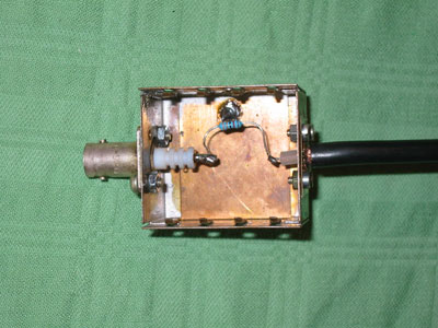 Inside the limiting resistor
box.
Inside the limiting resistor
box.
Post
formatting considerations
Even
after a well performed formatting process occasional arcing can occur
in a transmitting tube. Some people claim that a transmitting tube will
adopt to the actual working voltage and by that give occasional arcs
even at the normal operating voltage. I have not been able to confirm
this thesis, but some unexpected arcs may be explained by this idea. In
order to limit the consequences from such an arc some precaution can
be taken.
I have had arcing several times in different types
of tubes and PA's but have not yet had one tube destroyed from the
arcing. The three phase high voltage power supply I am using has about
10 uF capacitance and an transformer capable of delivering
>4.5 kVA (about 45 kg of iron). Fuses on both the incoming three
phase (3 x 400 V) and on the outgoing high voltage line. The incoming
fuses have never opened up, but that have the fuses on the high voltage
line. In the high voltage line is also a low inductance current
limiting resistor of
100 ohm with a power rating of 100 W.
It seams like if you have a current limiting series
resistor and well fused you can limit the devastation from an arc in
the transmitter tube.
Heater
voltage considerations
A
transmitter tube is sensitive to the applied heater voltage. You
should always follow the recommendations of the manufacturer closely.
Running a tube on a too high heater voltage will shorten the life of
the tube. Running the tube on a too low heater voltage can poisoning
the cathode. This is especially true for the Thoriated Tungsten cathode
type.
Running a transmitting tube on UHF close to it's upper
frequency limit
may cause back-heating of the control grid and by that emission from
the grid. This can be harmful to the tube. In order to avoid
back-heating you can slightly lower the heater voltage. Many
manufacturer of tubes have clear recommendations of how much to lower
the heater voltage.
One way of finding the optimum heater voltage for a tube is
to run the
tube with a standing current (I.E. Ia =100 mA) and vary the heater
voltage while monitoring the change of the standing current. You will
find that the standing current will vary with the heater voltage in an
non-linear way. By finding the "knee voltage" and using a heater
voltage just above the knee you will get the most operating time out of
the
tube without sacrifice performance.
It is an good idea to limit the rush-in current when applying
heater
voltage to a cold tube. Connect a series resistor on the primary side
of your heater transformer and short it out after 5 to 10 seconds of
heater time. Using a variable resistor in the primary circuit of the
heater transformer gives the possibility to adjust the heater voltage.
If the heater transformer is used for generating other voltages as well
it may not be possible to vary the resistance in the primary circuit.
In this case you need to have the resistors in the secondary circuit of
the heater transformer. Always let the tube pre-heat the specified time
before applying anode current and RF to the tube.
A too high heater voltage can induce arcing in the tube. This
may be a
effect of back-heating.
Transmitter
tube cooling considerations
Adequate
cooling of a transmitting tube is essential. Always follow the
manufactures recommendations about the required amount of cooling air.
More cooling air than recommended is just fine. But, how to know how
much fan is enough?
In the data sheet of many transmitting tubes you can find
graphs on
back pressure versus air flow as well as dissipated power. The same can
be found on many fans. By checking these against each other you can
find out if the fan is enough for the application.
There
are three major fan types; radial, diagonal and axial. The radial fans
have a 90 degree angle between air inlet and outlet and gives in
general the best back pressure. The axial fans have a 0 degree angle
between air inlet and outlet and does not give a high back pressure.
The diagonal fan have
a 0 degree angle between air inlet and outlet but a different angle on
the rotor blades compared to the axial fan. The diagonal fan gives in
general a better back pressure than the axial fan.
It is also very easy to measure back pressure by using a non
opaque
plastic tube. Form the plastic tube to a U-shape and mount it on a
stand. Fill the U with water so you get the two water surfaces at a
convenient hight. Attach one end of the plastic tube to the high
pressure side of the tube. Measure the hight difference of the two
water surfaces. This measure in mm is the back pressure in mmVp.
You
can find many different units for both back pressure and air flow and
it is not always easy to convert between them. Here is a small guide to
these conversions:
10 mmVp = 1 mbar = 100 Pa = 0.39 inches of water
1 m3/min = 60 m3/h
= 1000 l/min = 35.3 cfm
For
my 23 cm PA I am using the below combination of fan and tube. For 12 V
of fan voltage (at low speed dashed curves) I measure 15 mmVp that
corresponds to an air flow of 150 m3/h and at 11
V (full speed solid curve) 28 mmVp corresponding to ~200 m3/h.
 Air flow
versus back pressure for Bosch BPA 12 V radial fan (part number 0 130
007 804)
Air flow
versus back pressure for Bosch BPA 12 V radial fan (part number 0 130
007 804)
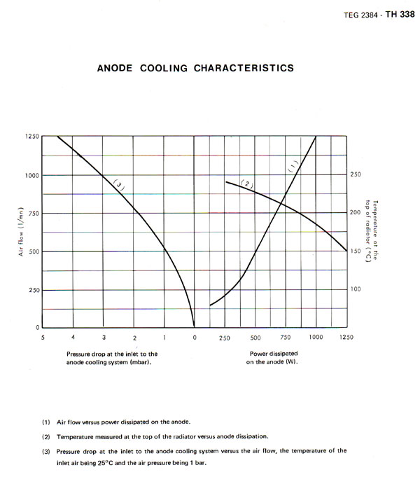 Air
flow versus back pressure for Thompson TH338 triode
Air
flow versus back pressure for Thompson TH338 triode
A
simple way of measuring back pressure is to use this back
pressure gauge. It uses physical constants to measure the back pressure
and is by this self calibrating.
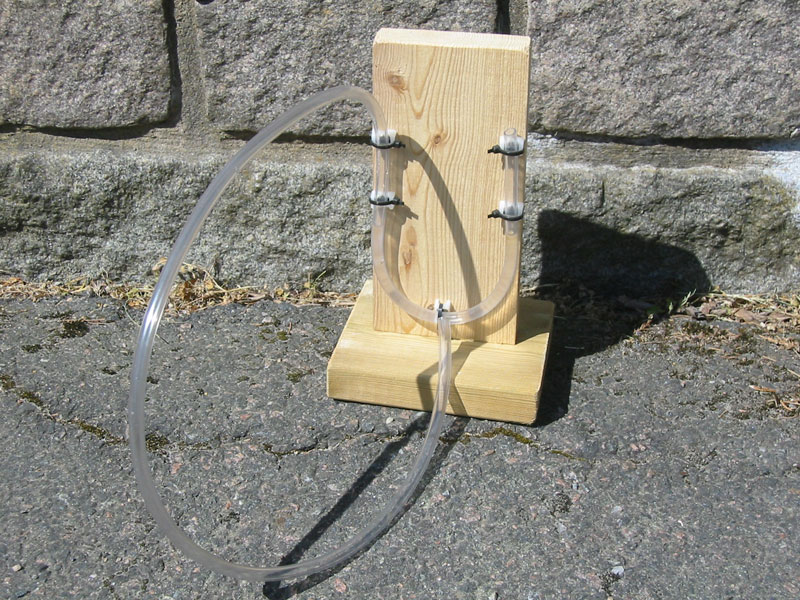 Back
pressure gauge
Back
pressure gauge
Connect
the end of the plastic tube of the back pressure gauge to the back
pressure test outlet of the pressurized anode compartment and read the
difference between the two water surfaces with the fan running. This is
the back pressure in mmVp or in inches of water if you prefer that.
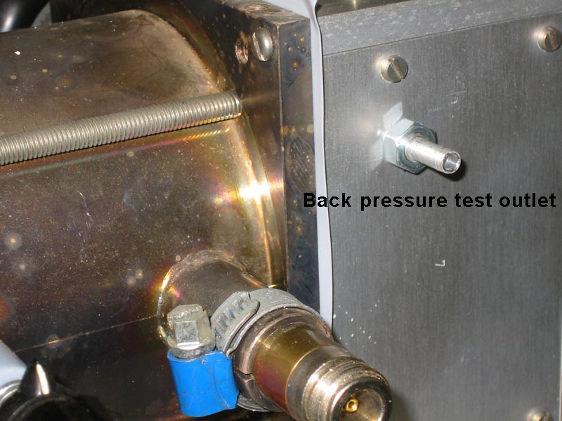 Back
pressure test outlet
Back
pressure test outlet
Links
SM5BSZ
home page: http://www.sm5bsz.com/
About tubes / valves
in general: http://www.thevalvepage.com/index.shtml
About "getters": http://www.thevalvepage.com/valvetek/getter/getter.htm
References:
[1]
Care and feeding of POWER GRID TUBES, Laboratory staff , Varian,
Eimac Division, 1967, Library of Congress No. 67-30070

Updated July 27th, 2009.
http://www.2ingandlin.se/SM6FHZ.htm